A perfectly fabricated pickling tank can fail within two years if installed incorrectly — and the failure won’t be a material defect; it will be a cracked weld caused by an uneven foundation or a leaking nozzle stressed by rigid pipework. Across our project support visits, installation errors account for a measurable fraction of early-life tank problems. The tank itself was engineered to handle hot acid, but the concrete under it was poured with a 6mm dip, or the discharge pipe was hung from the tank nozzle instead of an independent support. These are avoidable errors, and they are almost never covered by warranty.
This article lays out the pickling tank installation best practices that directly determine whether your tank reaches its 10–15 year design life or requires weld repairs by year three. It covers the four engineering interfaces where most problems occur: the concrete foundation, the connecting pipework, the fume extraction system, and the pre-commissioning water test. Every recommendation is based on installation procedures developed across 500+ installations and on the failure investigations we have conducted when a tank leaked prematurely. For readers needing to first specify a tank correctly, our steel wire pickling tank selection guide covers the upstream design decisions.
Table of Contents
- Foundation Requirements: Flatness, Continuous Support, and Drainage
- Pipework Connection: Thermal Expansion and Stress Isolation
- Fume Extraction: Duct Material, Slope, and Support
- Lifting, Positioning, and Protecting Welds During Installation
- Pre-Commissioning: The 24-Hour Water Test and Final Checks
- What Goes Wrong: Installation Failures We Have Investigated
- Frequently Asked Questions
Foundation Requirements: Flatness, Continuous Support, and Drainage
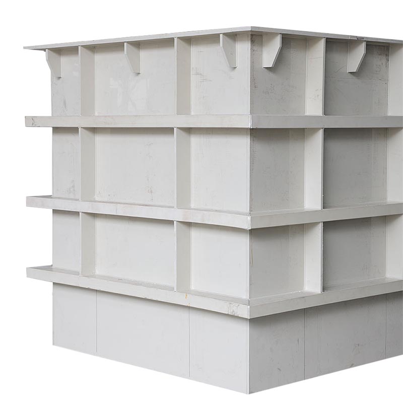
A PP pickling tank is not a self-supporting rigid structure like a steel vessel. It is a semi-flexible shell that relies on a flat, continuous base to distribute hydrostatic load evenly. The foundation is not just a surface to place the tank on — it is a load-bearing element of the tank system.
Flatness Tolerance: ≤3 mm per Metre
The concrete plinth must be leveled to a maximum deviation of 3 mm per linear metre in any direction, and no more than 6 mm across the entire footprint of the tank. This tolerance comes from field observation: a local depression of 5 mm under a 15mm PP bottom sheet can create a point load that concentrates stress at the adjacent bottom corner weld. Over months of thermal cycling and hydrostatic load, that concentrated stress initiates micro-cracks in the weld. We have documented this exact failure mode in three separate installations where the foundation was poured to a general “level” standard without quantified verification.
Continuous Support: No Gaps, No Point Loads
PP tank bottoms must be supported across their entire area. The concrete surface should be smooth and free of protruding aggregate, bolt heads, or formwork debris. A 5–10 mm thick rubber or closed-cell polyethylene pad placed between the concrete and the tank bottom is recommended — it absorbs minor surface irregularities and distributes load. The pad must be continuous; strips or isolated pads create the point loads they are intended to prevent.
Chemical Containment and Drainage
The foundation area should include a chemical-resistant containment curb around the tank perimeter, sized to hold at least 110% of the tank volume in the event of a catastrophic leak. The containment floor should slope to a sump for controlled drainage. Acid-resistant coatings (epoxy or vinyl ester-based) on the concrete within the bund are mandatory — uncoated concrete will be attacked by HCl spills and lose structural integrity. Reference ISO 12573:2011 for the general principle that the tank support must maintain its load-bearing properties under all foreseeable chemical exposure.
Anchoring (If Required)
Most PP pickling tanks are gravity-stabilized and do not require bolted anchorage. If seismic restraint is specified, anchor brackets must be welded to the tank wall at the factory, not on site, and the connection to the foundation must allow for vertical thermal expansion of the tank wall. Rigid bolting that prevents vertical movement will cause the wall to buckle as the tank heats up from ambient to 65°C.

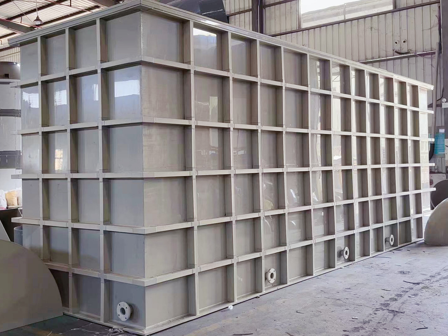
Pipework Connection: Thermal Expansion and Stress Isolation
The pipework connected to a pickling tank is the source of more installation-related leaks than any other factor. A PP tank expands when filled with 65°C acid. If the pipework does not accommodate this movement, the tank nozzle becomes a fixed point against which the expanding or contracting tank wall pushes. The result is a cracked weld at the nozzle-to-wall interface — a repair that requires emptying the tank and grinding out the original weld.
Flexible Connectors at Every Nozzle
Every pipe connection to the tank — inlet, outlet, overflow, drain, recirculation — must include a flexible element within 300 mm of the nozzle flange. Acceptable flexible elements are PTFE or EPDM bellows, or a short section of flexible reinforced hose rated for the acid and temperature. A rigidly bolted pipe that runs 3 metres to the first support bracket is not acceptable; it acts as a lever on the nozzle. This is especially important for larger nozzles (≥80 mm diameter) where the leverage force is higher.
Independent Pipe Supports
No pipe weight, pump weight, or valve actuation force should be carried by the tank nozzle. All pipework must be supported by independent frames or hangers that are anchored to the building structure or to separate concrete pedestals — never to the tank itself. The first pipe support must be located within 1 metre of the flexible connector. A common mistake is to use the tank nozzle as the pipe support for a heavy acid circulation pump mounted directly to the nozzle flange. This arrangement transmits pump vibration and thermal cycling stress directly into the weld. For custom tank configurations with multiple nozzles, our custom plastic tank engineering package includes nozzle load limits that the piping designer must respect.
Thermal Expansion Calculation
PP has a coefficient of linear thermal expansion of approximately 0.15 mm/m/°C. A 4-metre-long PP tank heated from 25°C to 65°C will expand by 4 × 0.15 × 40 = 24 mm in length. The pipework flexible connectors must accommodate this full range of movement without placing load on the nozzle. If the connecting pipe is also PP, its own thermal expansion must be calculated and managed with expansion loops or additional bellows.
Fume Extraction: Duct Material, Slope, and Support
A pickling tank without effective fume extraction exposes operators to acid mist and corrodes the building structure. The extraction system begins at the tank hood and extends to the scrubber — and the installation details in between determine whether it works for a decade or leaks condensate onto the factory floor after six months.
Duct Material: PP, with a Slope
Extraction ducting carrying HCl mist must be fabricated from PP — not PVC, which softens above 60°C and can deform under the warm, saturated air stream. All horizontal duct runs must slope at least 1:100 back toward the tank so that condensed acid drains into the tank rather than pooling in low points and eventually leaking through joints. Drain points with U-traps should be provided at any unavoidable low points in the duct run.
Independent Duct Supports
Like the process pipework, the extraction duct must be supported independently from the tank hood. The hood itself may be integrated into the tank design (recommended for factory-fabricated units), but the duct running from the hood outlet to the scrubber must be hung from the building structure. Duct weight pulling on the hood can distort the hood-to-tank weld over time.
Scrubber and Fan Sizing Verification
Verify that the extraction fan capacity matches the open surface area of the tank. A recommended capture velocity is 0.5–1.0 m/s across the tank opening. Under-sizing the fan is a common cost-cutting decision that results in visible acid mist escaping the hood during production. For plants in jurisdictions with active regulatory inspection — such as DENR in the Philippines or PCD in Thailand — inadequate fume capture can trigger a non-compliance finding during an unannounced site visit.
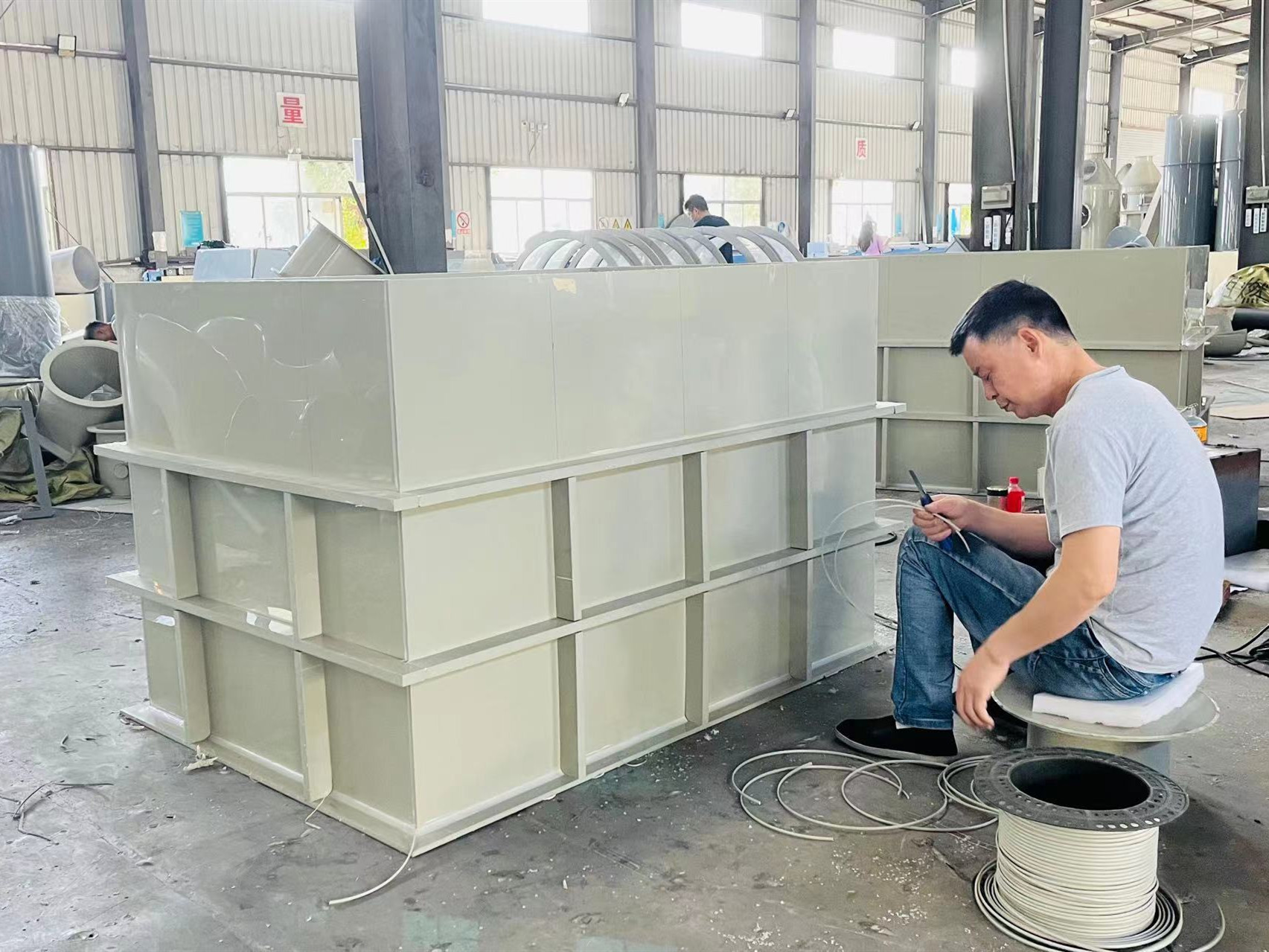
Lifting, Positioning, and Protecting Welds During Installation
The tank arrives at site as a completed, factory-tested assembly. The installation team’s first job is to get it onto the foundation without damaging it — and this is where forklift tine marks on tank bottoms and lifting sling abrasions on external welds occur.
Lifting Arrangements
PP tanks must be lifted using fabric slings (not steel chains or wire rope) positioned at designated lifting points. If the tank was not fabricated with integral lifting lugs, slings should be wrapped around the tank body with adequate padding and spreader bars to prevent the slings from pinching the sidewalls. Under no circumstances should a forklift tine be inserted under the tank bottom without a protective pad — the point load can crack the bottom sheet or the bottom corner weld before the tank ever sees acid.
Positioning and Leveling
Once the tank is on the rubber pad on the concrete plinth, check level with a spirit level in both directions. If shimming is required to achieve the ≤3 mm/m flatness, place full-area shim plates under the rubber pad — never place isolated shims directly under the tank bottom. Adjust until the tank sits fully in contact with the pad across its entire footprint. For a pickling tank system with multiple cells, each cell must be leveled independently while maintaining the correct weir height alignment between cells.
Protecting Existing Welds
No site welding should be performed on a factory-tested tank without an approved procedure and qualified welder. If a nozzle must be added or modified on site, the affected area must be spark-tested after welding and a localized hydrostatic or water test performed before commissioning. Site welding on PP tanks using unqualified personnel and no post-weld NDT is the direct cause of leaks that manifest within the first year of operation. The hot-gas welding process, per TWI guidelines, demands controlled conditions and qualified procedures — conditions rarely met on an active construction site.
Pre-Commissioning: The 24-Hour Water Test and Final Checks
Before a single litre of acid enters the tank, a series of pre-commissioning checks must be completed and documented. Skipping these steps, or shortening their duration, transfers installation risk into operational risk.
24-Hour Water Fill Test
Fill the tank completely with clean water — not process water, which may contain contaminants — and hold for a minimum of 24 hours. This test serves a different purpose than the factory hydrostatic test: it verifies that the installation foundation has not distorted the tank and that field-connected pipework does not impose load on the nozzles. After 24 hours, inspect every weld, nozzle, and flange with a flashlight. Any seepage or drip is a fail. Measure the tank level; a drop in water level indicates a leak. Document the test with dated photographs and a signed checklist.
Pipework Leak Test
Pressure-test all connected pipework with water at the system’s design pressure before connecting it to the tank nozzles. This isolates pipe leaks from tank leaks — when the system is first filled, a leak at a pipe flange that drips down the tank wall can be misdiagnosed as a tank weld leak, triggering unnecessary investigation.
Fume Extraction Functional Test
Run the extraction fan and verify capture velocity at the hood opening using an anemometer. A simple tissue test — hold a tissue at the hood inlet; it should be pulled firmly against the grille — is acceptable for daily checks post-commissioning, but the initial verification should be quantitative.
Heating System Dry Run
With the tank filled with water, bring the heating system online and raise the water temperature to the design operating temperature. Monitor the tank for any signs of uneven expansion, particularly at nozzle penetrations and the tank-to-hood interface. Verify that flexible pipe connectors compress and extend without binding. This thermal dry run identifies problems that a cold water test cannot.
What Goes Wrong: Installation Failures We Have Investigated
These cases come from site visits where a tank was leaking, and the root cause was traced to installation, not fabrication.
Foundation Settlement — Galvanizing Plant, Philippines
A 10,000L PP pickling tank was placed on a concrete plinth that developed a 12 mm settlement at one corner within the first six months of operation. The tank’s bottom corner weld at the low corner was forced into tension as the tank effectively spanned the settled area. Within 14 months, the weld developed a through-crack, and acid seeped into the containment bund. The foundation issue was traced to poorly compacted backfill under the plinth. The tank itself had passed all factory NDT and the initial 24-hour site water test — but the foundation was not stable over time. The corrective action required jacking the tank, regrouting the plinth, and repairing the weld — a two-week outage that cost far more than proper site preparation would have.
Rigid Pump Connection — Steel Wire Line, India
A circulation pump was mounted directly to the tank discharge nozzle using a rigid flanged connection, with no flexible element and no independent pump support. After approximately 3,000 hours of operation (less than 6 months), the nozzle-to-wall weld developed a leak. The pump vibration and the thermal expansion cycles had fatigued the weld. The repair required draining the tank, cutting out the damaged nozzle, re-welding with a reinforcement pad, and re-installing the pump with a flexible connector and an independent support frame. The plant lost five days of production for a problem that a flexible connector would have prevented entirely.
Site Welding Without NDT — Electroplating Shop, Thailand
A contractor added a small drain nozzle to an existing PP tank on site to suit a revised floor drain layout. The welding was done by the site mechanical crew, not a qualified PP welder, and no spark test was performed afterward. The tank was filled, and the nozzle showed no visible leak during the initial water test. After three months of HCl service at 55°C, a fine acid mist began escaping from a pinhole in the site weld, corroding nearby structural steel. The pinhole was detected by a spark test only after the tank was drained and cleaned — it would have been caught immediately had the same test been required before commissioning. For electroplating lines where multiple tanks are interconnected, our plastic plating tank designs include all nozzles factory-installed and tested, eliminating the need for site welding of pressure boundaries.
Frequently Asked Questions
What is the most critical foundation requirement for a PP pickling tank?
A flat, continuous concrete plinth with a maximum deviation of 3 mm per linear metre. PP tanks are flexible structures that depend on uniform support to distribute the hydrostatic load of the acid bath. Any depression under the tank bottom creates a gap that forces the tank wall to span the void, concentrating stress at the bottom corner welds. This stress, combined with thermal cycling and the weight of the acid, can initiate weld cracking that leads to leaks. A 5–10 mm rubber pad between the concrete and the tank bottom further ensures even load distribution.
Why do I need flexible connectors on every pipe connected to a PP pickling tank?
A PP tank expands significantly when heated — approximately 24 mm over a 4-metre length when going from 25°C to 65°C. If connecting pipes are rigidly attached without flexible elements, the tank nozzle is forced to act as a fixed anchor point. The resulting stress on the nozzle-to-wall weld can cause cracking. Flexible connectors (PTFE or EPDM bellows, or reinforced acid-resistant hose sections) within 300 mm of the nozzle flange absorb this movement and protect the weld. Every nozzle — inlet, outlet, overflow, drain — requires its own flexible connector.
Can I weld additional nozzles onto a PP pickling tank at the installation site?
Site welding on a factory-tested PP tank should be avoided whenever possible. If it is absolutely necessary, the welding must be performed by a qualified operator using an approved procedure, and the new weld must be 100% spark-tested and hydrostatically tested before the tank is put into service. Unqualified site welding is a leading cause of first-year leaks, because construction-site conditions rarely provide the controlled environment required for hot-gas extrusion welding of PP.
How long should the pre-commissioning water test last?
A minimum of 24 hours at full fill level. This duration is necessary to detect slow seepage through any micro-porosity or installation-induced stress that opens under sustained hydrostatic load. After 24 hours, inspect every weld, nozzle, and flange visually, and measure any water level drop. A passing test requires zero visible leakage and no measurable level loss. Document the test with dated photographs and a sign-off sheet — this documentation may be required for warranty validation and regulatory compliance.
What fume extraction duct material and slope should I use for HCl pickling tanks?
PP ducting is recommended for HCl mist extraction because it is chemically inert to hydrochloric acid and retains its mechanical properties up to 80°C. PVC ducting softens above 60°C and is not recommended for heated pickling applications. All horizontal duct runs must slope at least 1:100 back toward the tank to prevent condensed acid from pooling in low points and eventually leaking through joints.
Should a pickling tank be anchored to the concrete foundation?
Most PP pickling tanks are gravity-stabilized and do not require bolted anchorage. The weight of the filled tank (acid plus tank structure) provides stability under normal operating conditions. If seismic restraint is required by local building code, anchor brackets must be designed to allow vertical thermal expansion of the tank wall. Rigid bolting that prevents the tank from expanding upward as it heats will cause the wall to buckle. Any anchorage brackets should be welded to the tank at the factory, not on site, to ensure proper weld quality and spark testing.
Get Installation Support for Your Pickling Tank Project
Every pickling tank installation has site-specific conditions — foundation type, existing pipework, seismic zone, regulatory jurisdiction — that influence the final installation specification. If you are planning a pickling tank installation, our engineering team can review your site drawings and provide a project-specific installation procedure with foundation tolerance requirements, pipe connection details, and a pre-commissioning checklist. Contact us to request an installation support package.
Written by Corbin, Applications Engineer at XICHENG EP LTD.
With 10+ years designing and supporting the installation of PP pickling tanks across 30+ countries and 500+ installations, this article draws directly from on-site commissioning reports, failure investigations, and feedback from plant engineers who operate these tanks daily. Every installation failure described here reflects an actual event documented in our project database.